Building a 14" Dobsonian mounted Newtonian telescope
Sometime in the early 70s I wanted to build my own telescope. I got as far as building the tripod mount with my dad before we abandoned the project.
Now 50 years later I have finally completed that challenge, thanks to Peter Clappison’s daughter, Jane, who sold me the mirror set for a nominal sum in 2023.
Peter commissioned the mirror set in the 1980s but didn’t have a chance to build his telescope before his untimely passing in 1989. Jane, after her mother’s passing in 2022, found the mirror and set out on a search for a suitable recipient.
Thanks also to John Dobson for simplifying telescope mount design in the 1980s and to Gordon Waite of Waite Research who makes some of the best looking telescopes around. My Dobs 14 is based on the style of the Waite Research scopes, but remains all my own work.
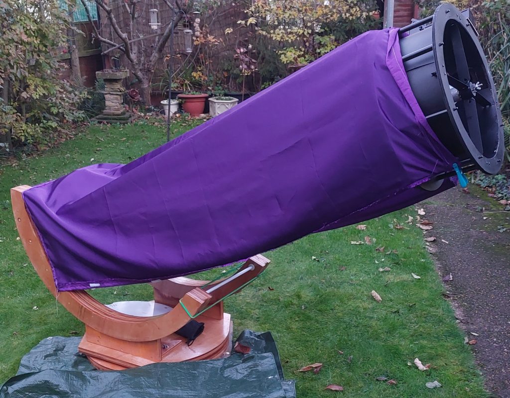
What's under the cover?
Early days: what to do with the glass?
Having acquired the mirror set in late 2023 it took me a while to decide what to do with them. What design style should I adopt? I decided early on not to take the easy route and build a classic box style dobs mount.
But it was spring 2024 before I discovered the Waite Research Renegade series of scopes and decided I wanted my scope to be built in that style.
I couldn’t simply buy a set of plans from Gordon as my mirror was smaller (14″) and much slower than the 16″+ F3.0 mirrors that Waite Research manufacture. The impact of this was a longer focal length, lighter primary mirror and a centre of balance much further out from the primary mirror. That’s why the curved bearings for my scope look so much bigger than those of the Waite Research scopes. Also, I think I over engineered the wood work a bit!
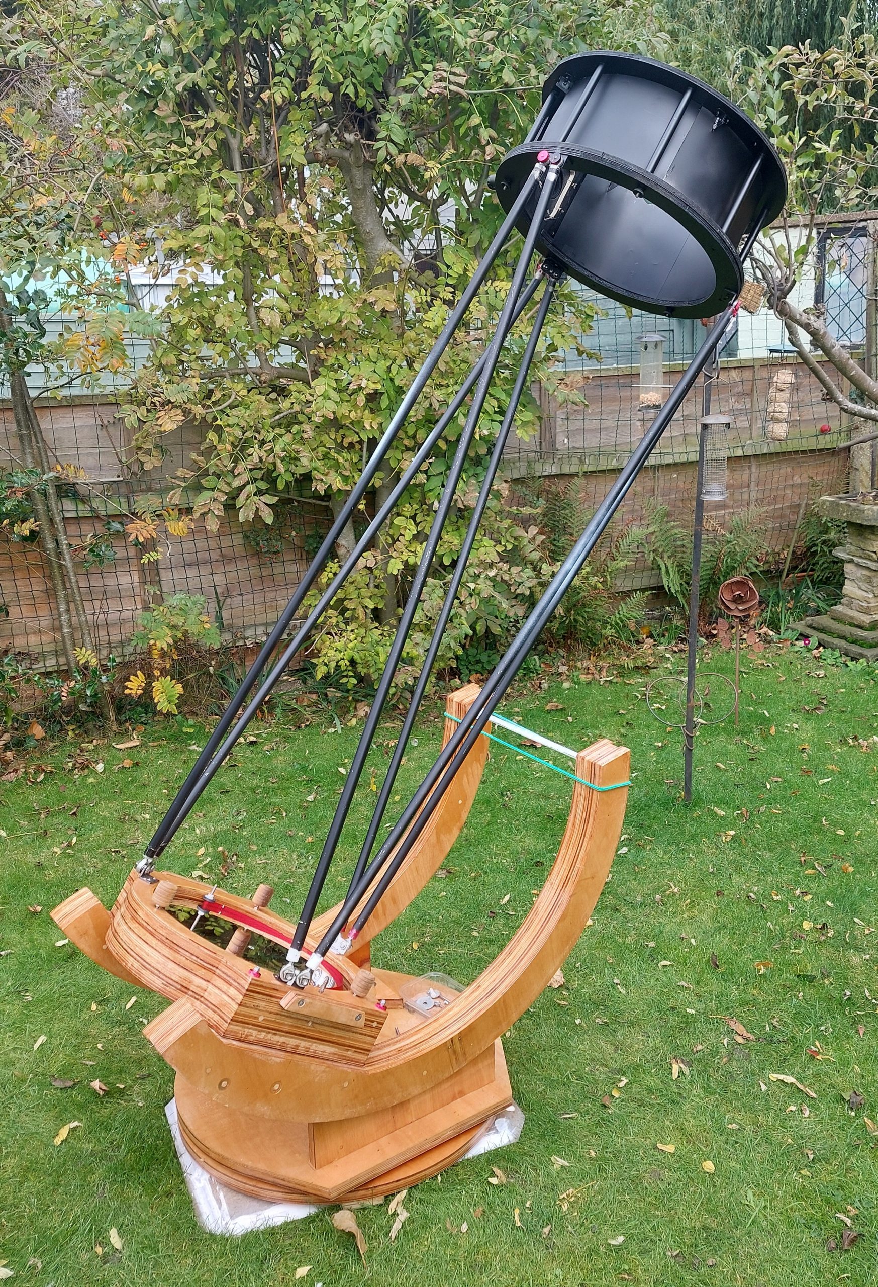
14" Dobs F5.8
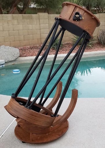
Waite Research Renegade Telescope
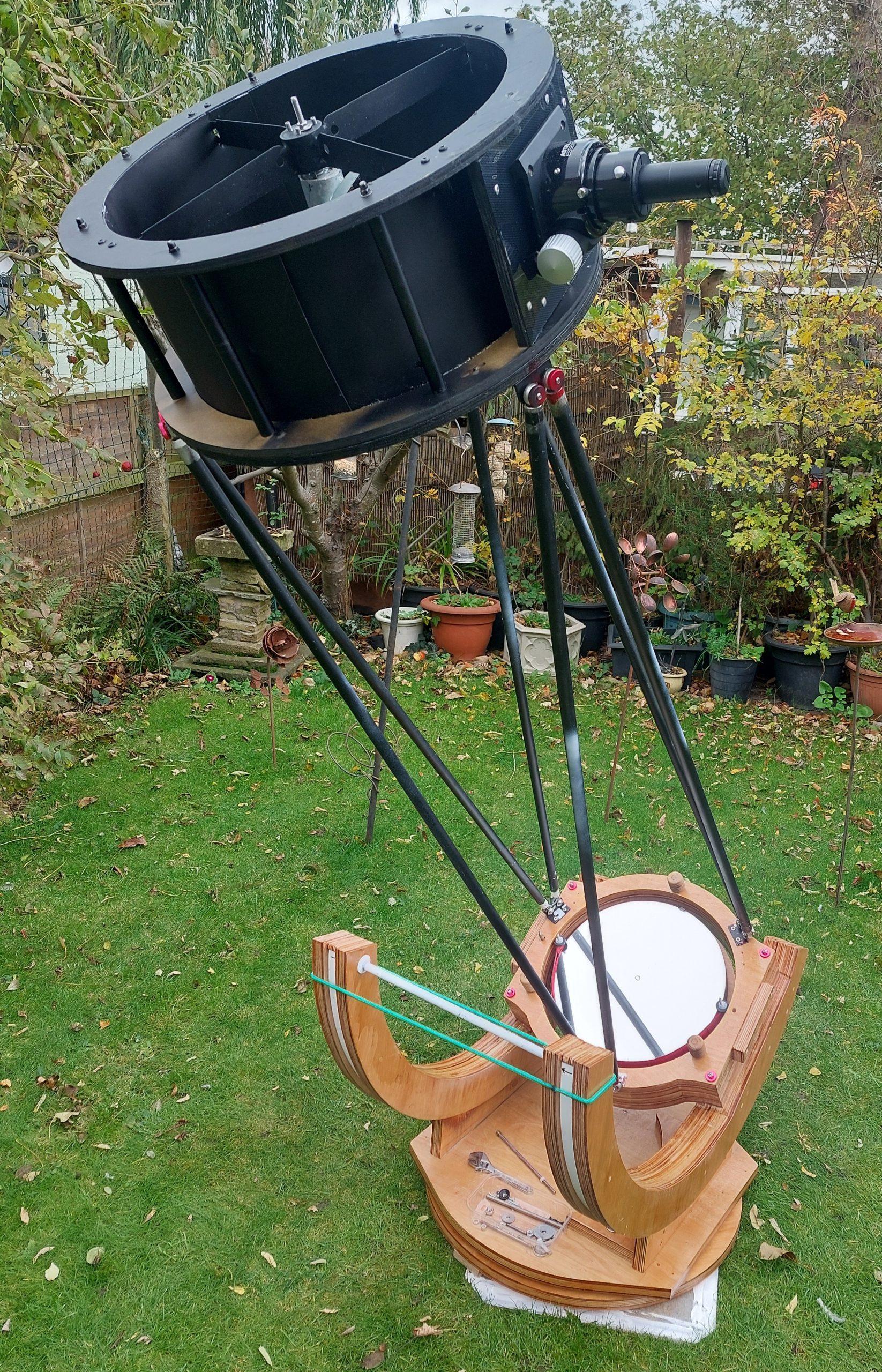
Dobs 14
Design Challenges
Originally I attempted to build the mount out of sawn timber, steam bent oak, wood glue and screws. I couldn’t get the level of finish that I wanted, but it did help me to test out some novel approaches before committing myself to the expense of hardwood plywood and a CNC cutting service.
Focal length: A torch, a sheet of white card, a tape measure and a long room gave me a good approximation of the focal length (1950mm) of the primary mirror. (See below).
Strut tubes: I happened to have some aluminium tubes on hand and decided to use those for the prototype. They worked so I kept them.
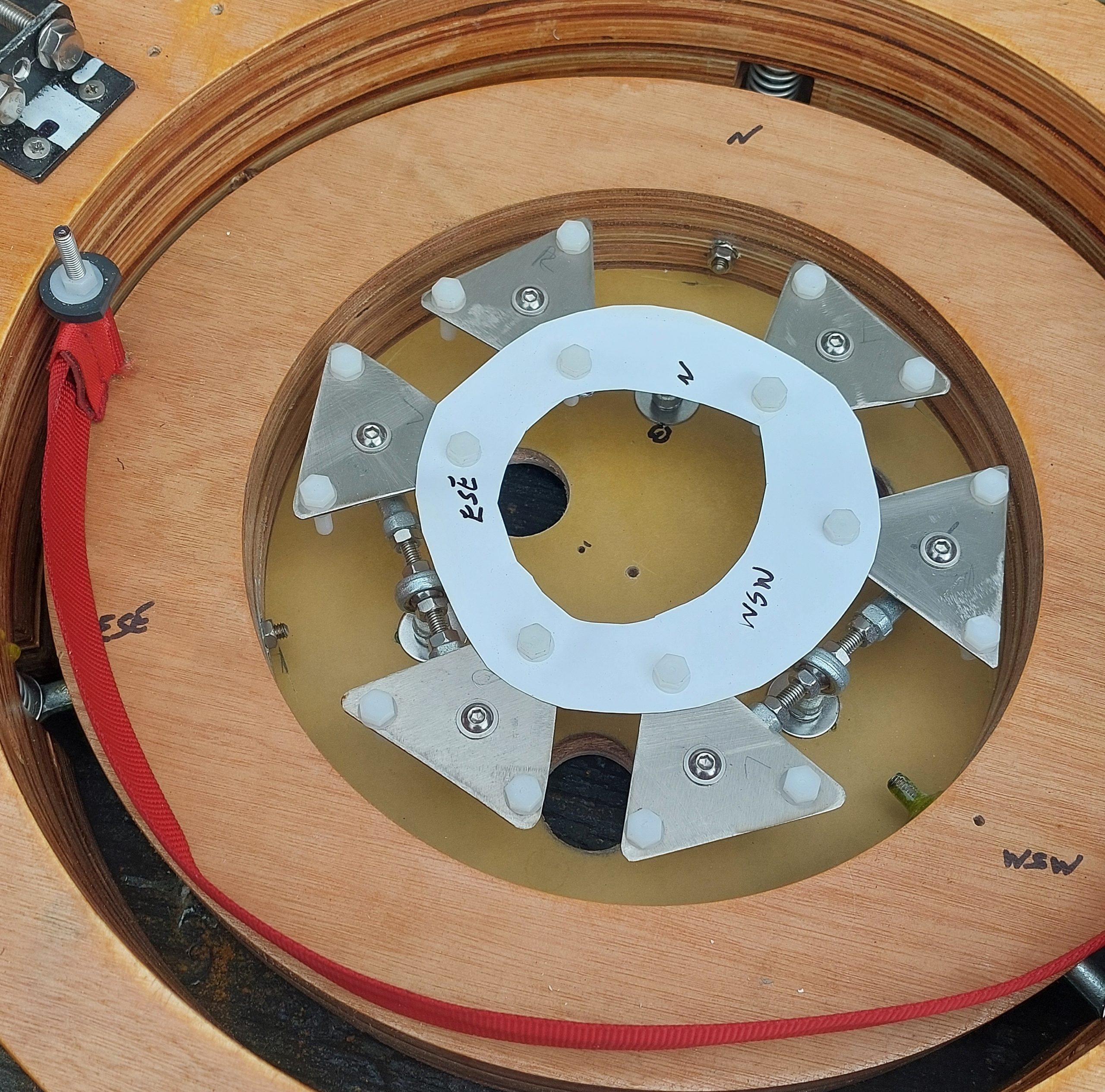
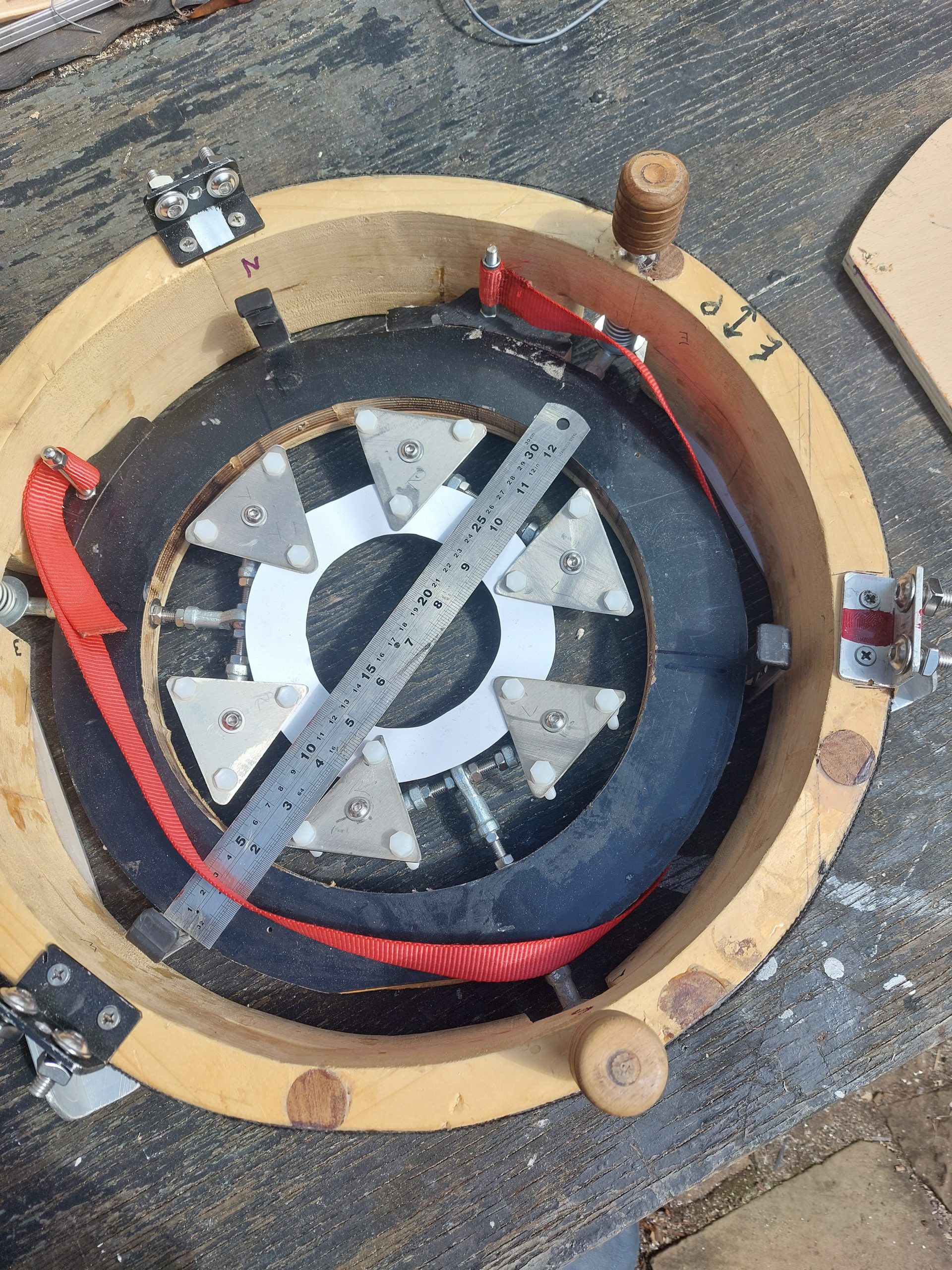
Primary Mirror cell: Not sure where I got the design from. I used an online programme to design the layout and then Ebay provided the parts to build it. I used 6mm stainless threaded rod and 6mm female rod end bearings to create an 18 point floating suspension. Key points of this final design include:
Each pair of triangular plates is supported on 6mm threaded rod post.
Each of the plates is kept aligned using the plastic paper ring.
Each of the 6 triangular plates can pivot to balance the weight carried by the 18 (in total) plastic bolt heads.
The support strap (seen in the left hand photo) is hung from the two support posts (more 6mm rod) which double up as locking lugs for the mirror cover.
I went for three sets of support poles, rather than the 4 sets used by Waite Research.
The collimation bolts are 6mm threaded rods that pull the mirror cell up against springs.
primary mirror parts
big altitude bearings
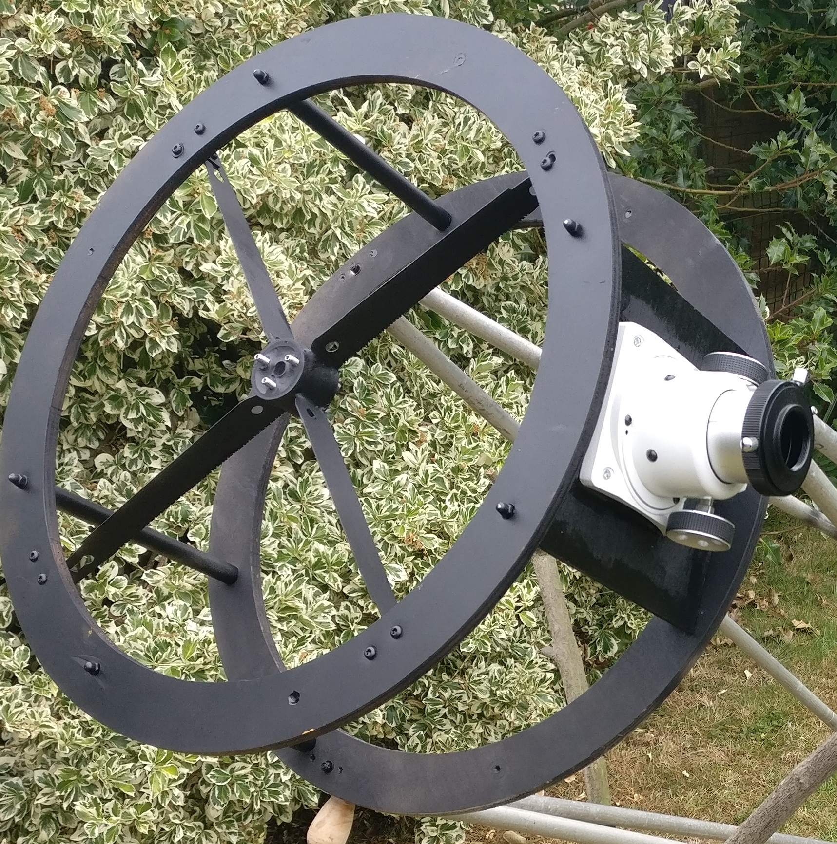
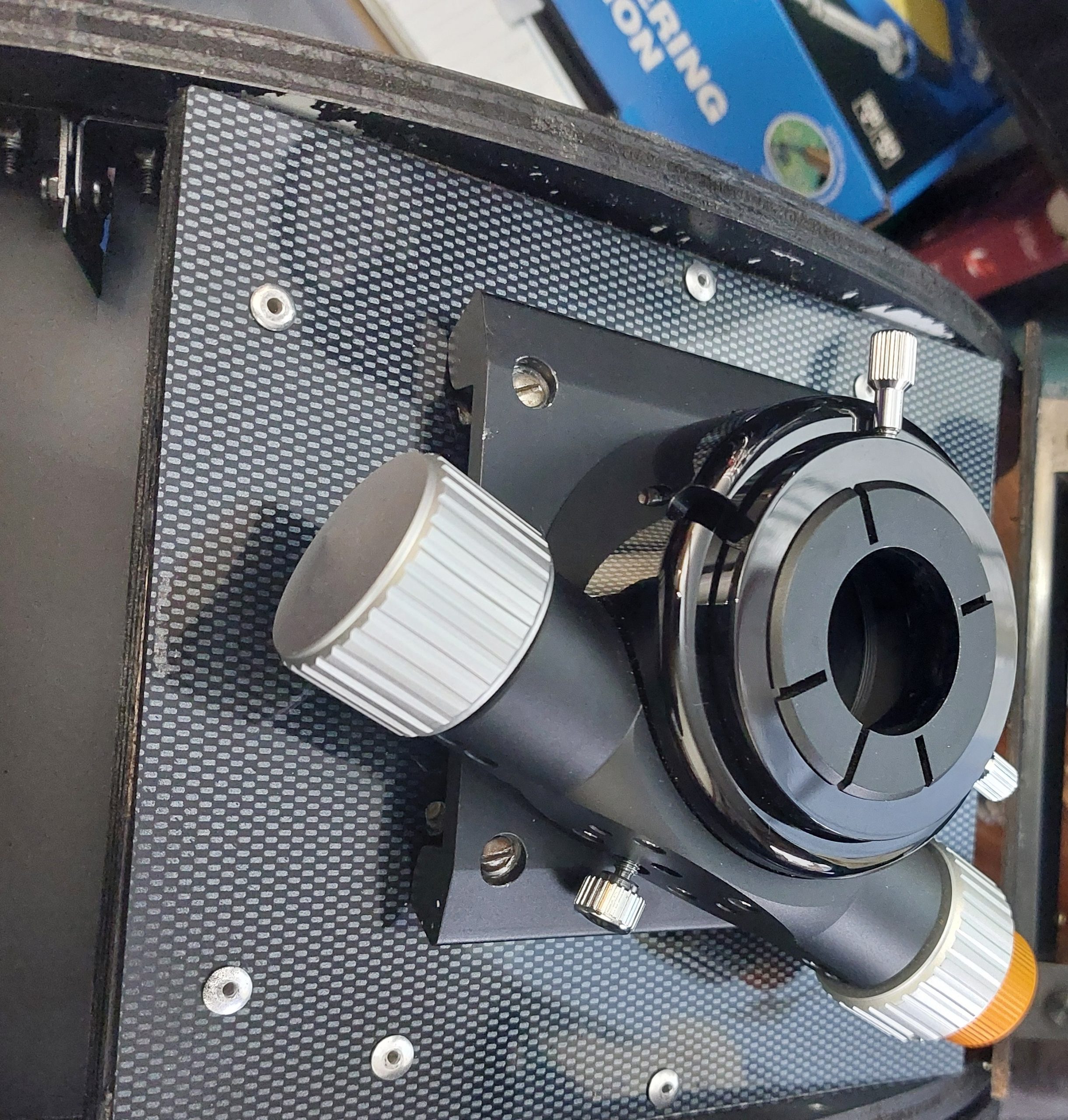
Secondary mirror assembly
Secondary Mirror Assembly
The challenges in building a secondary mirror assembly include keeping the weight down, where to find a big enough spider, attaching the struts, aligning the focuser, etc.
Keeping the weight down: This wasn’t as much of a problem as I thought. Due to a slight miscalculation in the size of the altitude bearings (too big) the scope was bottom heavy so I could add as much weight as I cared to the 2y mirror and still have it within balance.
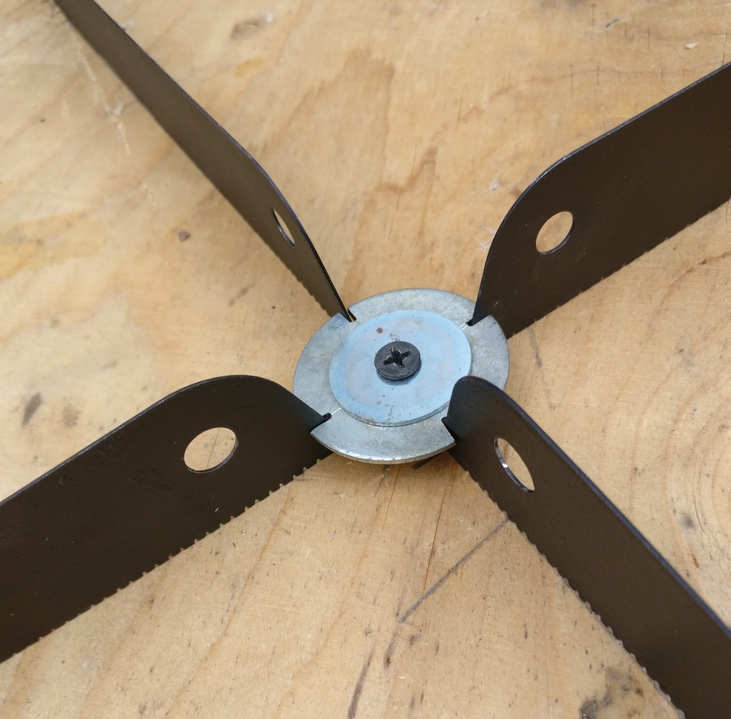
Big enough spider: In short I couldn’t find one. The 2y mirror assembly is oversized to reduce the overall height of the scope and finding a spider 450mm in diameter was impractical and unaffordable. So I made one. The vanes are 4 saw blades, Japanese style pull saw blades are thinner and turned out to be just the right size. Glued in place in the centre and fastened using simple brackets to the ring.
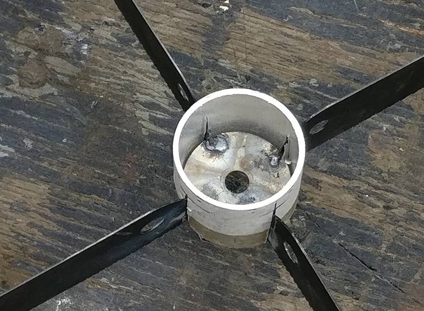
The mirror mount is aluminium tube filled with car body filler. The spider vanes were crudely welded to a steel washer and the whole assembly embedded in the car body filler inside the outer tube.
Holes for the centre bolt (oversized) and the three collimation bolts (undersized/friction fit) were drilled.
The mirror is glued to the mount using low vapour silicon rubber (beware the acetic acid fumes given off during curing as these can affect the mirror surface).
The top and bottom plywood rings are held together by thin walled aluminium tubes with 4mm threaded rod interrnally to hold it all tight.
To aid assembly of the scope there’s a mounting ring that’s attached to the main scope struts first. The secondary mirror assembly then bolts to this ring using three 4mm knurled nuts.
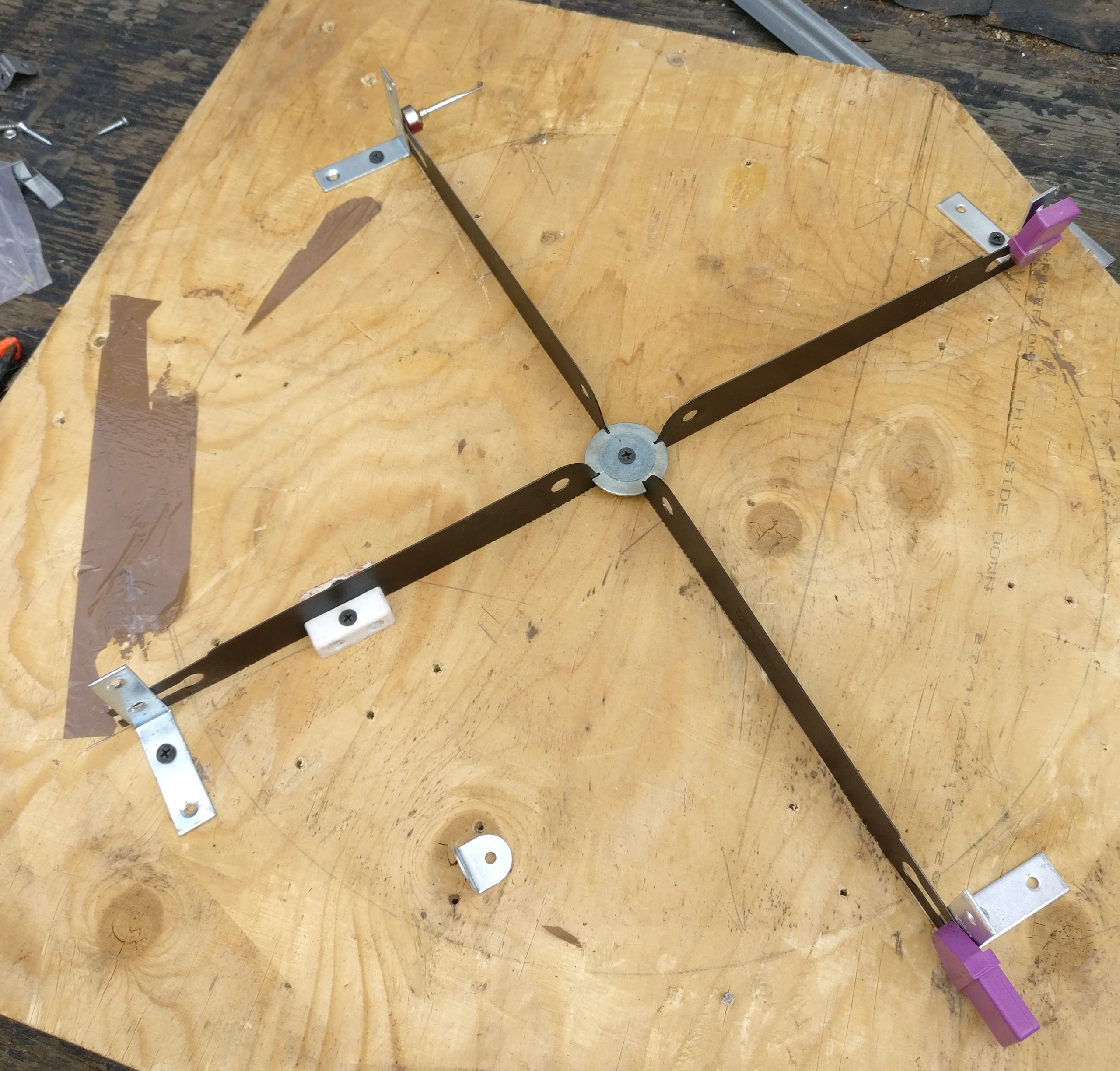
Showing 2y spider design
Prototype 2y cage, no mounting ring yet
central ball joint replaced by two bolts in final design.
This 2 speed focuser was my final choice
spider centre
spider bracket
Close up of spider assembly
The spider components consist of:
four saw blades. These are Japanese-pull-saw style blades. These blades are typically thinner than the more usual push saw blades.
Aluminium tubing. A straight section for the top, and a 45 degree section for the mirror mount.
Various washers, car body filler etc.
Method:
Grind down the cutting teeth of the saw blades a bit.
Assemble to four blades so they fit into slots cut into the large washer. The large washer is held ~4mm off the plywood base using a small nut.
Align everything at 90 degrees, ensure they are square, locked in place with brackets etc.
Spot weld the blades to the washer.
Assemble the wasker/blades inside the aluminium tube and fill with metal containing car body filler.
Drill holes for the 2y mirror bolt, alignment bolts etc. NB the alignment bolts are threaded into nuts glued into the body filler after setting.
Get ready for welding
align before welding
Fill with car body filler
Primary Mirror
The “traditional” material for the primary mirror cell is welded steel or aluminium, but I wanted to use wood if possible, at last for the visible parts.
The 18 point flotation cell is made up of 6mm rods and ball end joints, 3mm stainless sheet ( for the three clusters) and 6mm plastic bolts (the points of contact for the mirror). Only time will tell if it is rigid enough and if I should have gone for 8mm material.
A change from the prototype is to have the three clusters supported by a 12mm plywood disc rather than the straight through bolt arrangement you can see in the old style…image
Old style prototype primary mirror cell.
mirror cell parts
4x 25mm layers plywood
The “traditional” material for the primary mirror cell is welded steel or aluminium, but I wanted to use wood if possible, at least for the visible parts.
The 18 point flotation cell is made up of 6mm rods and ball end joints, 3mm stainless sheet and 6mm plastic bolts. Only time will tell if it is rigid enough and if I should have gone for 8mm rods.
A change from the prototype is to have the three clusters supported by a 12mm plywood disc rather than the straight through bolt arrangement you can see in the old style…image.
The plywood flotation cell “coller” (not sure what to call it) is 2 x 25mm plywood ovals glued together with 6mm rods sticking out. The rods are what the whole assembly is hung on and used to collimate the mirror.
Perhaps 8mm would have been better? Time will tell.
The oval shape allows enough space for two posts at 90 and 270 degrees. The sling hangs from these posts and is non adjustable.
primary mirror parts
Collimation bolts "pull" the mirror cell against springs.
mirror float post
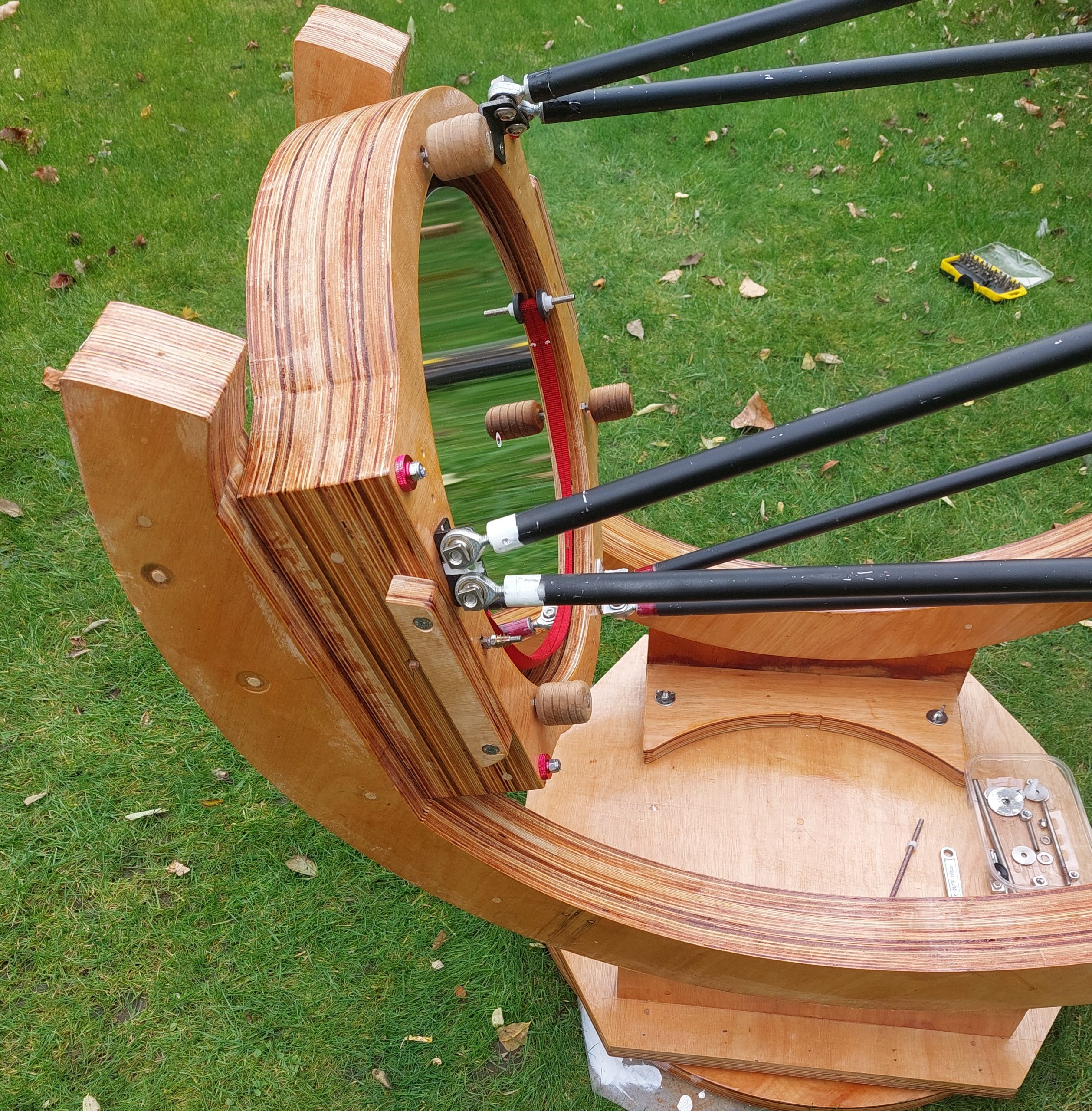
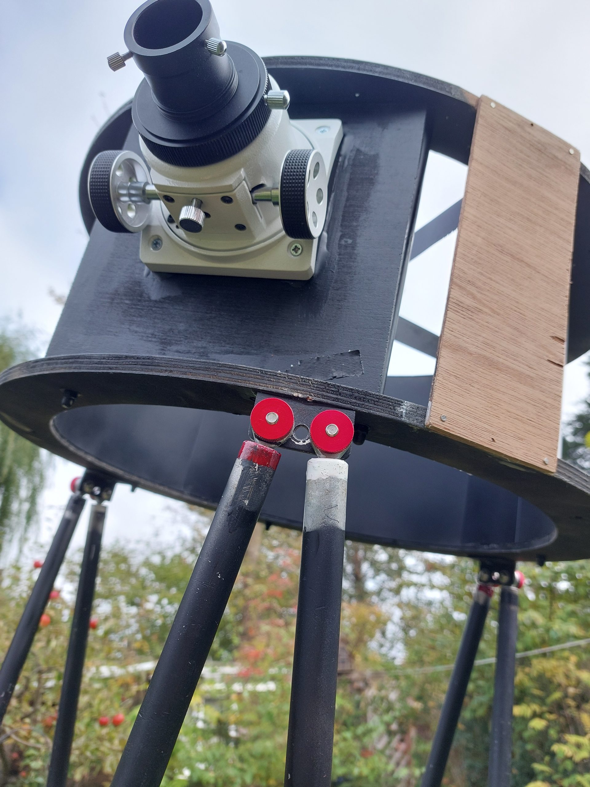
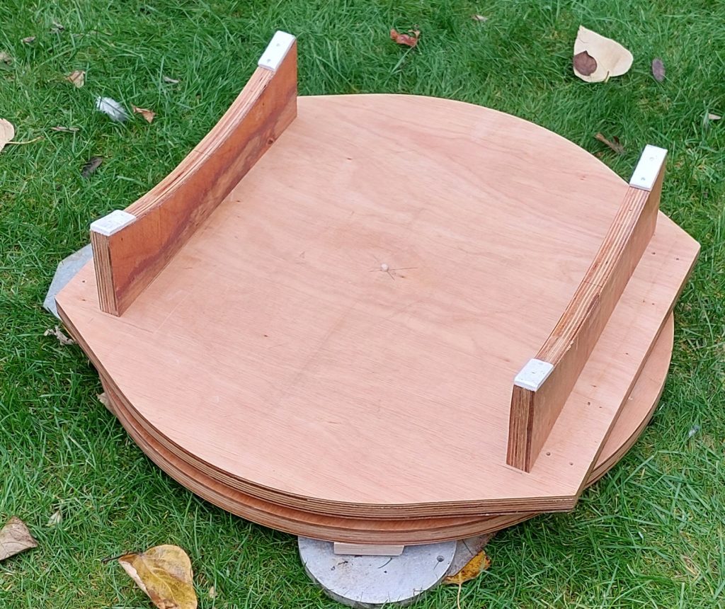
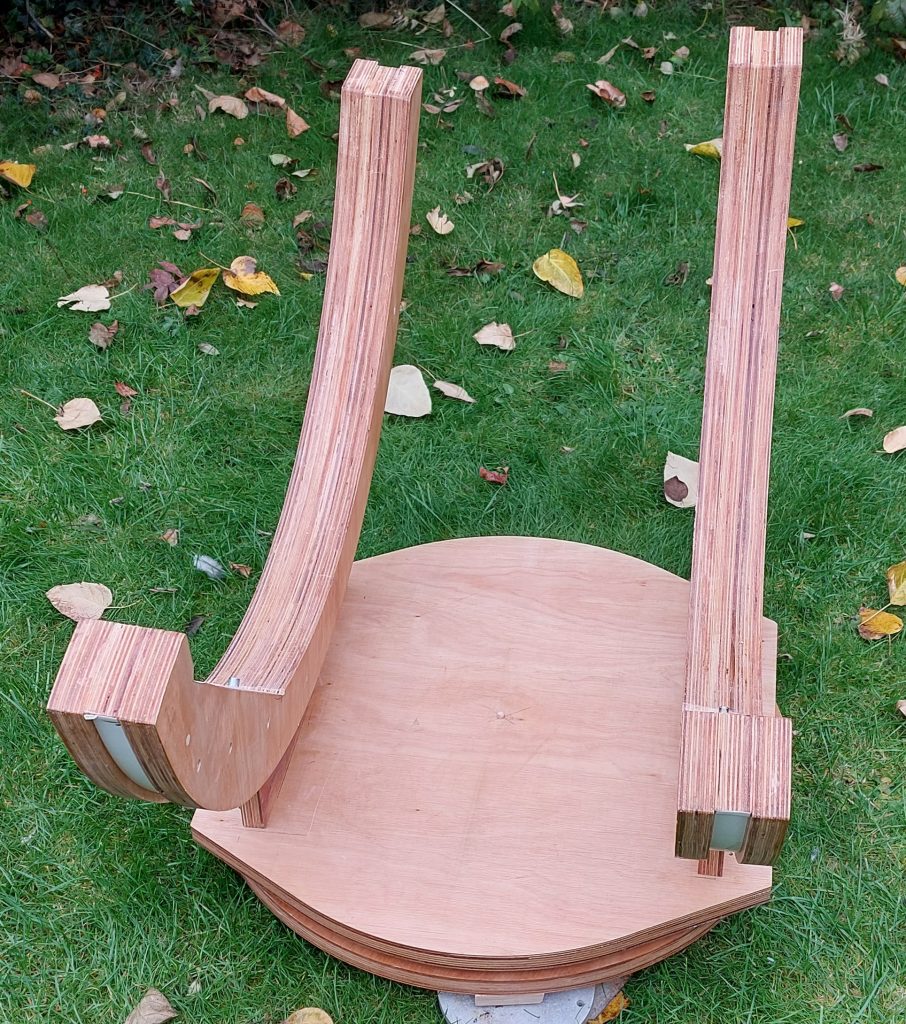
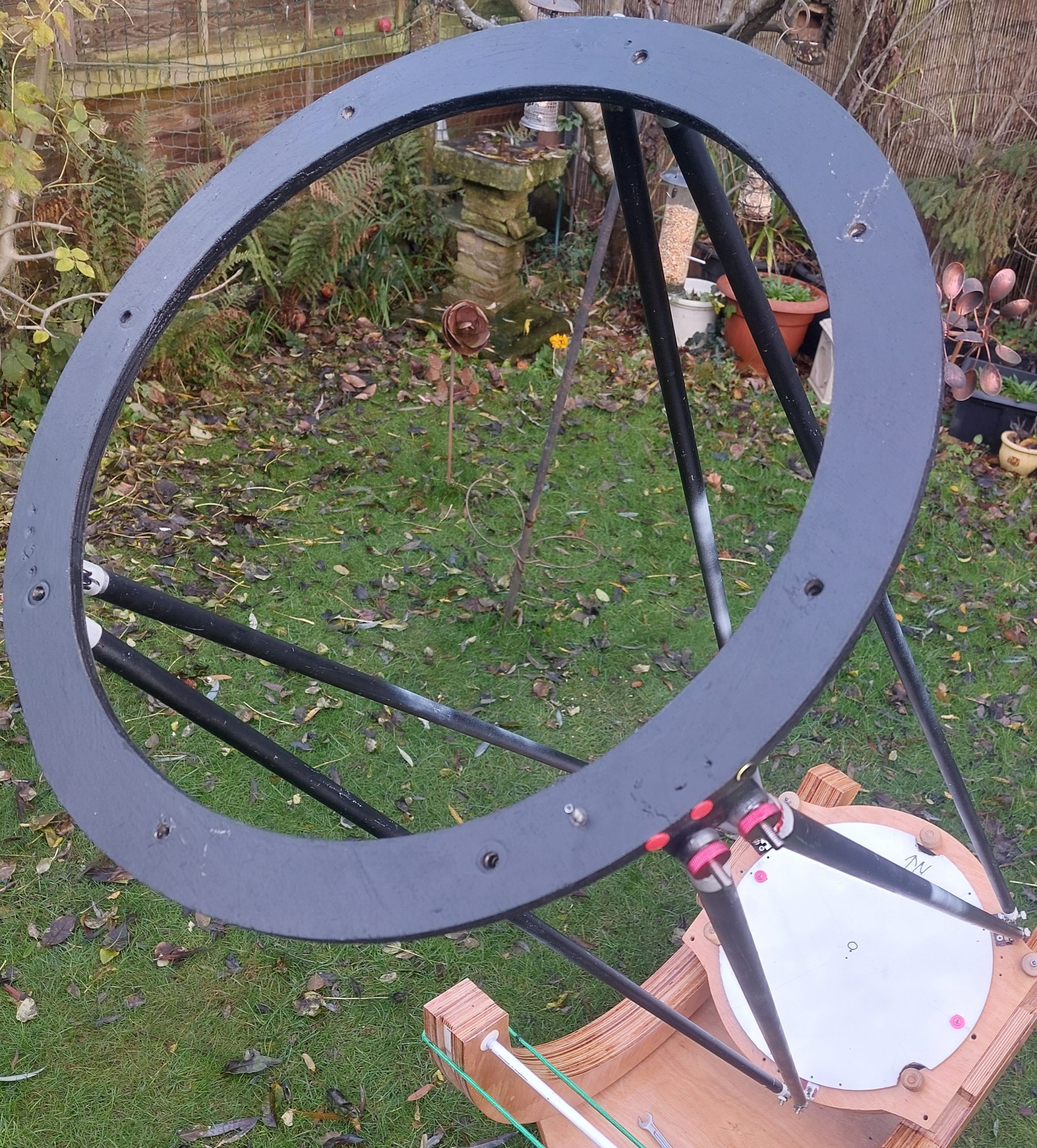
Altitude bearings
Big altitude bearings are very forgiving when it comes to weight distribution.
My bearings are too big I think, which is why the mirror box assembly sits on top of the bearings rather than between them as originally intended. This was a mistake, and I may change this in the future.
The idea is for the overall centre of gravity of the scope to be close to the centre of the arc that makes up the bearings.
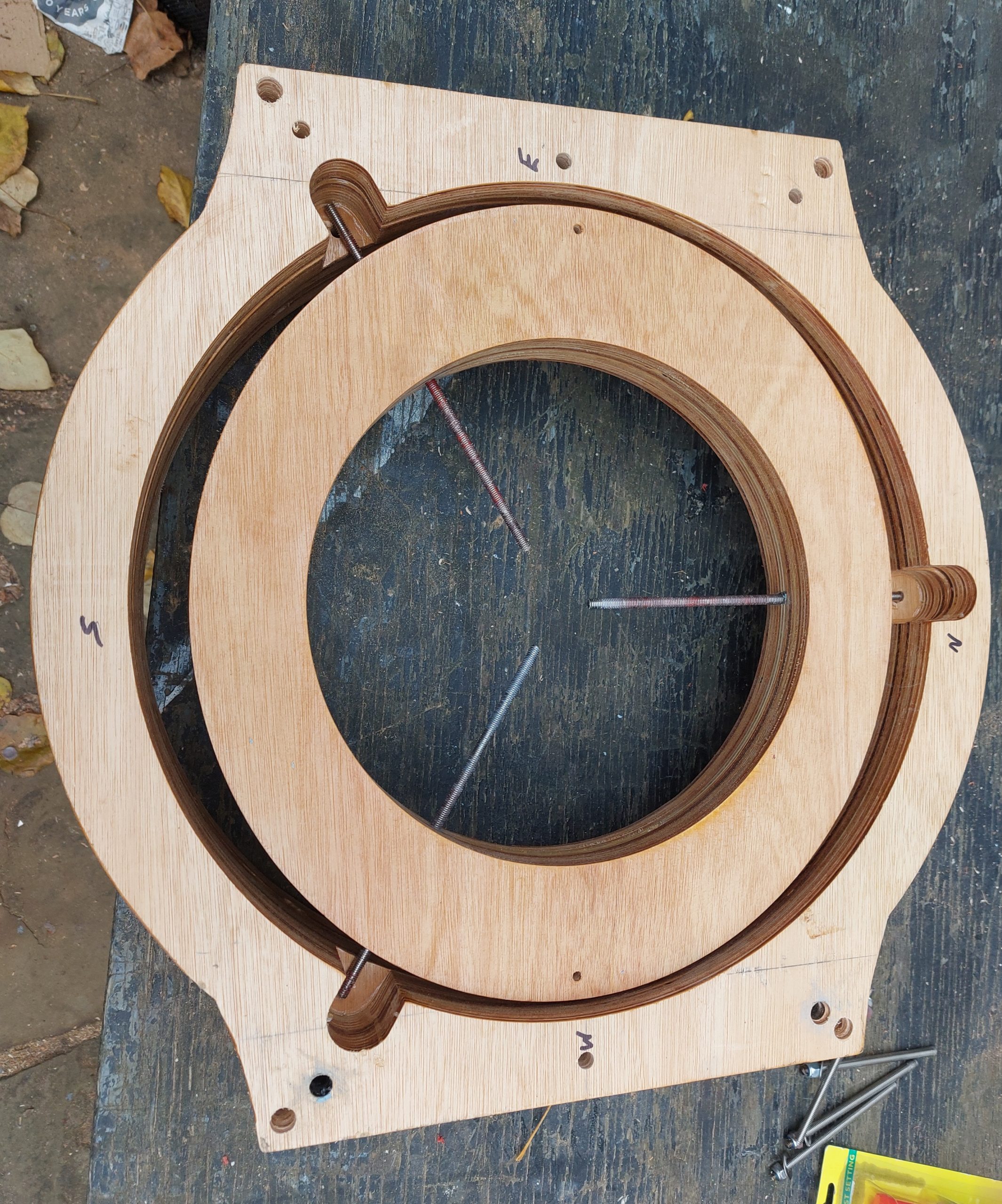
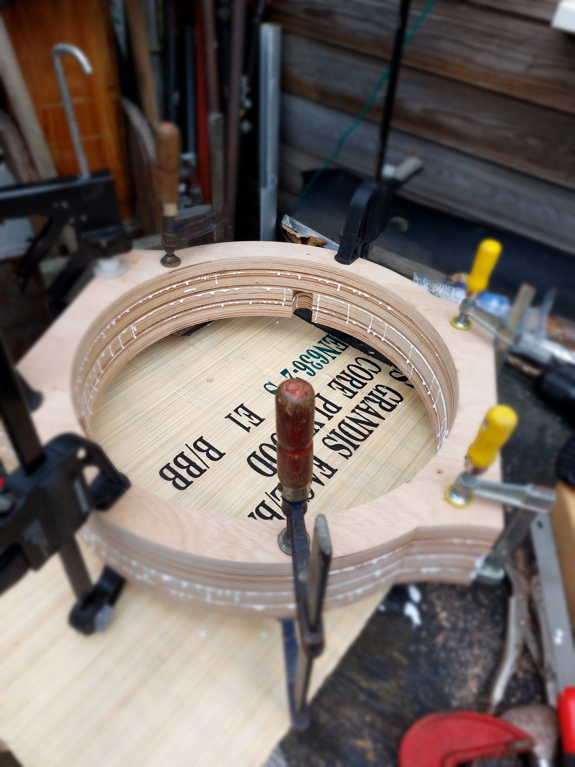
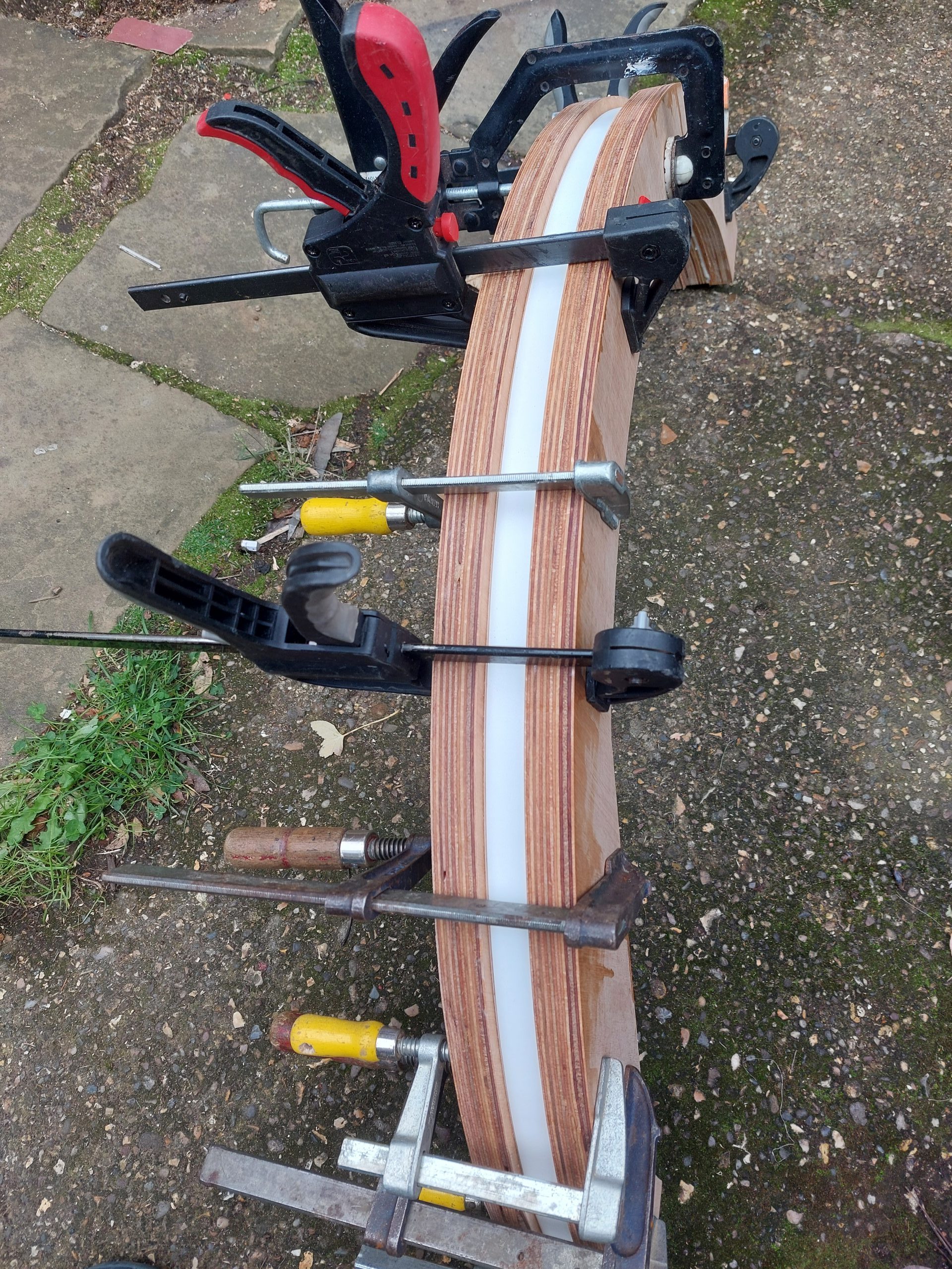
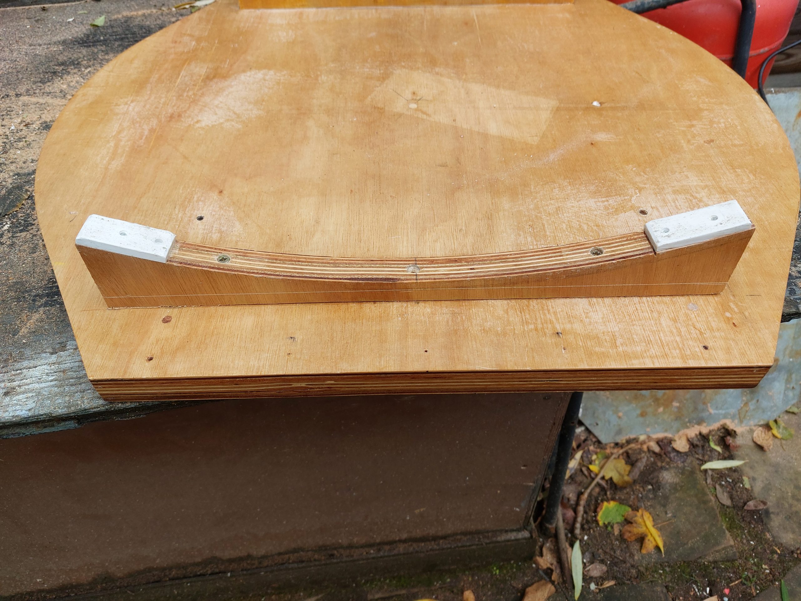
Each bearing is made up of a 25mm plywood piece with an internal diameter of 850mm. The two outside parts have an external diameter of 1000. The centre piece is 10mm smaller which produces a 5mm deep groove when they are all assembled.
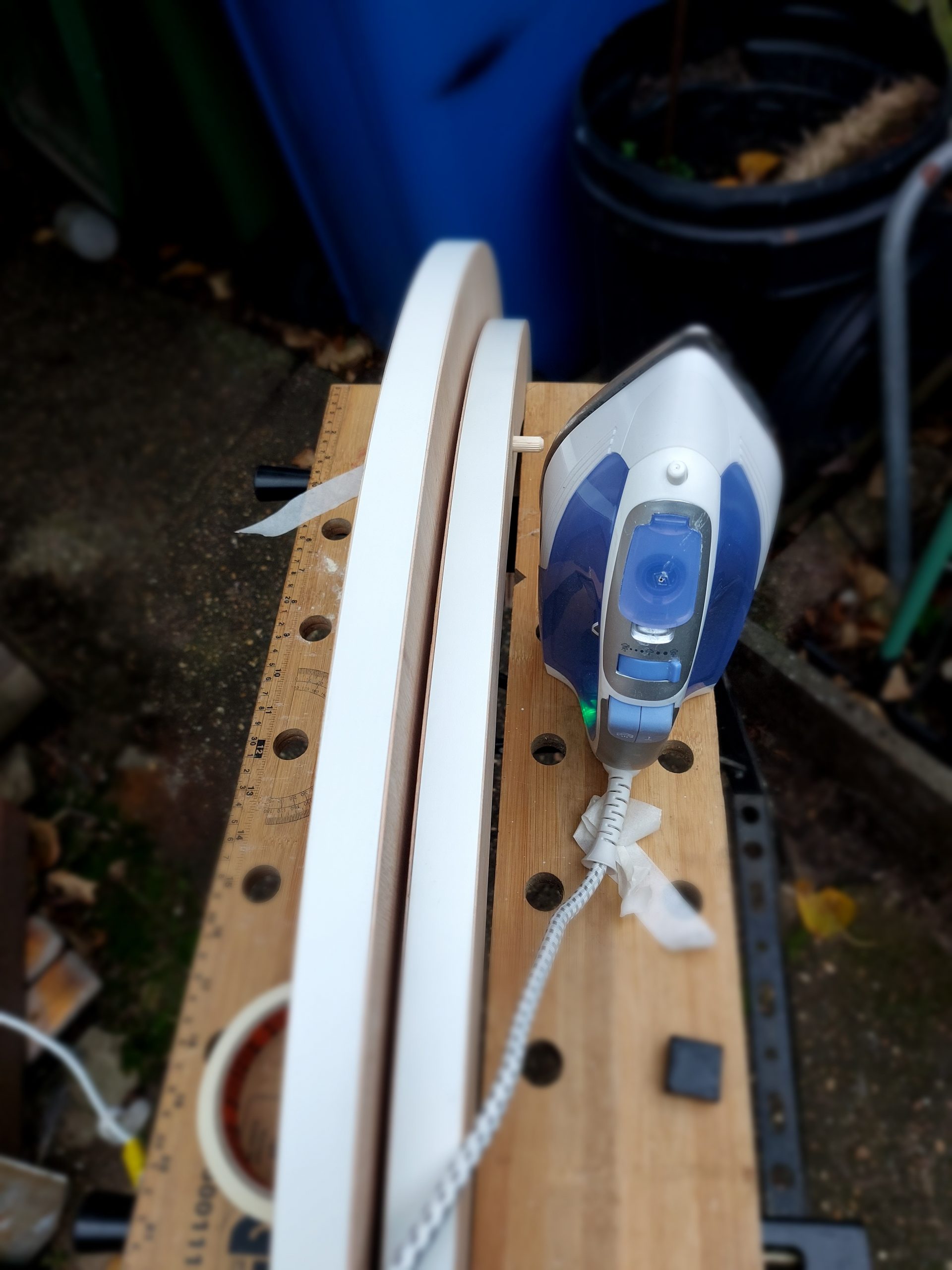
Before assembly, I ironed on a strip of formica to the smaller, centre parts to produce the smooth bearing surface once the three parts are glued to make up the altitude bearings.
20mm formica strip is the bearing surface.
Altitude bearing assembly
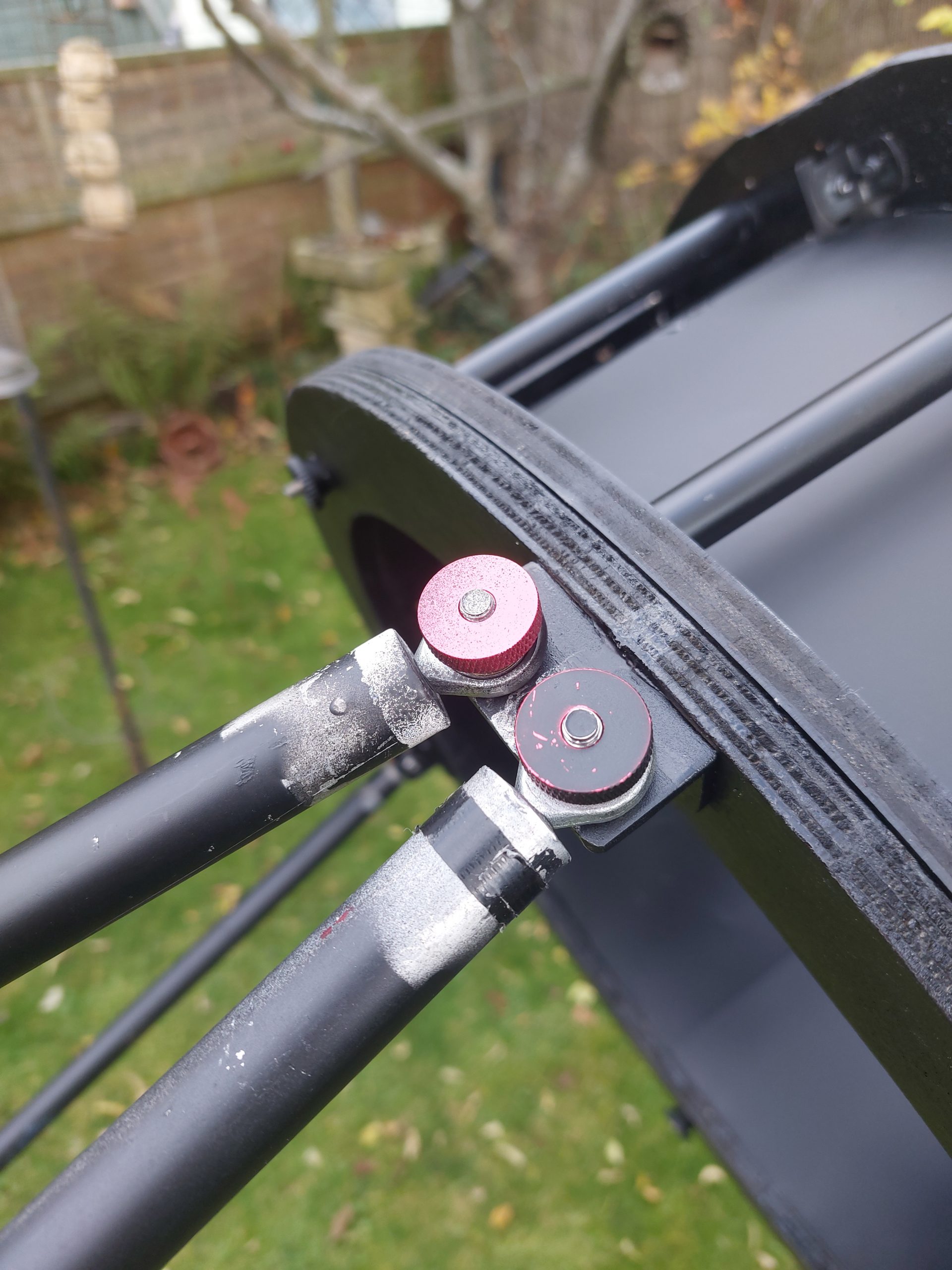
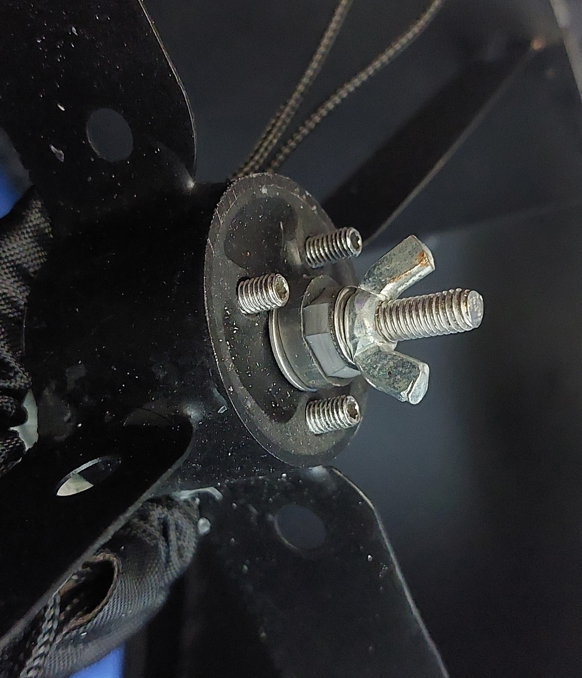
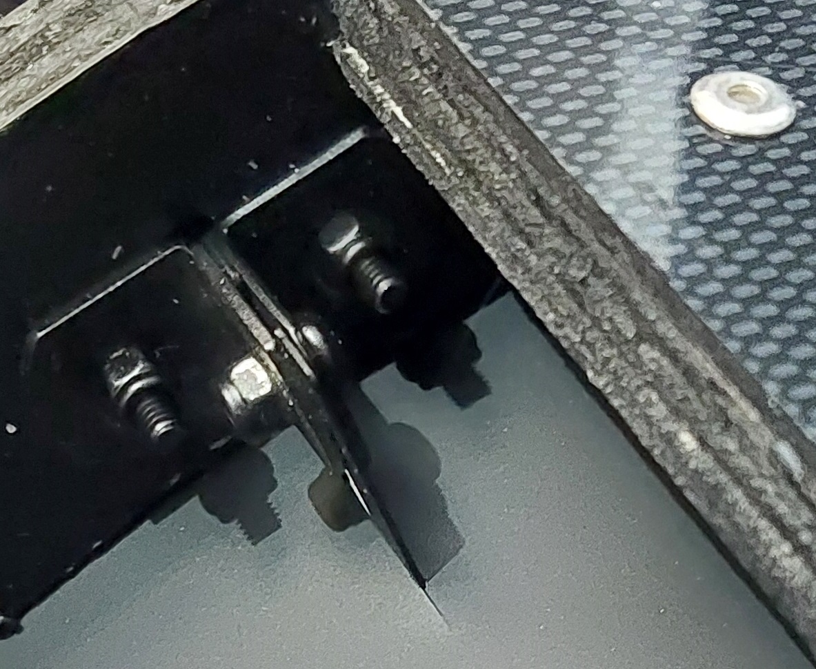
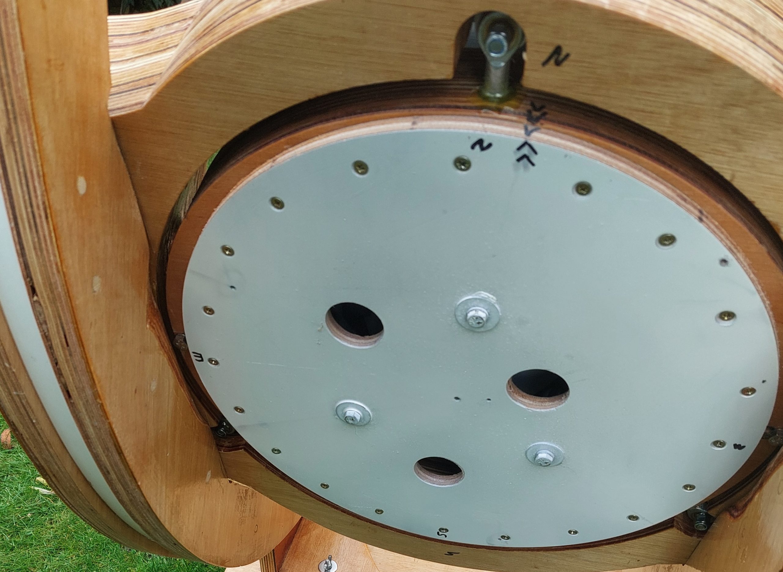
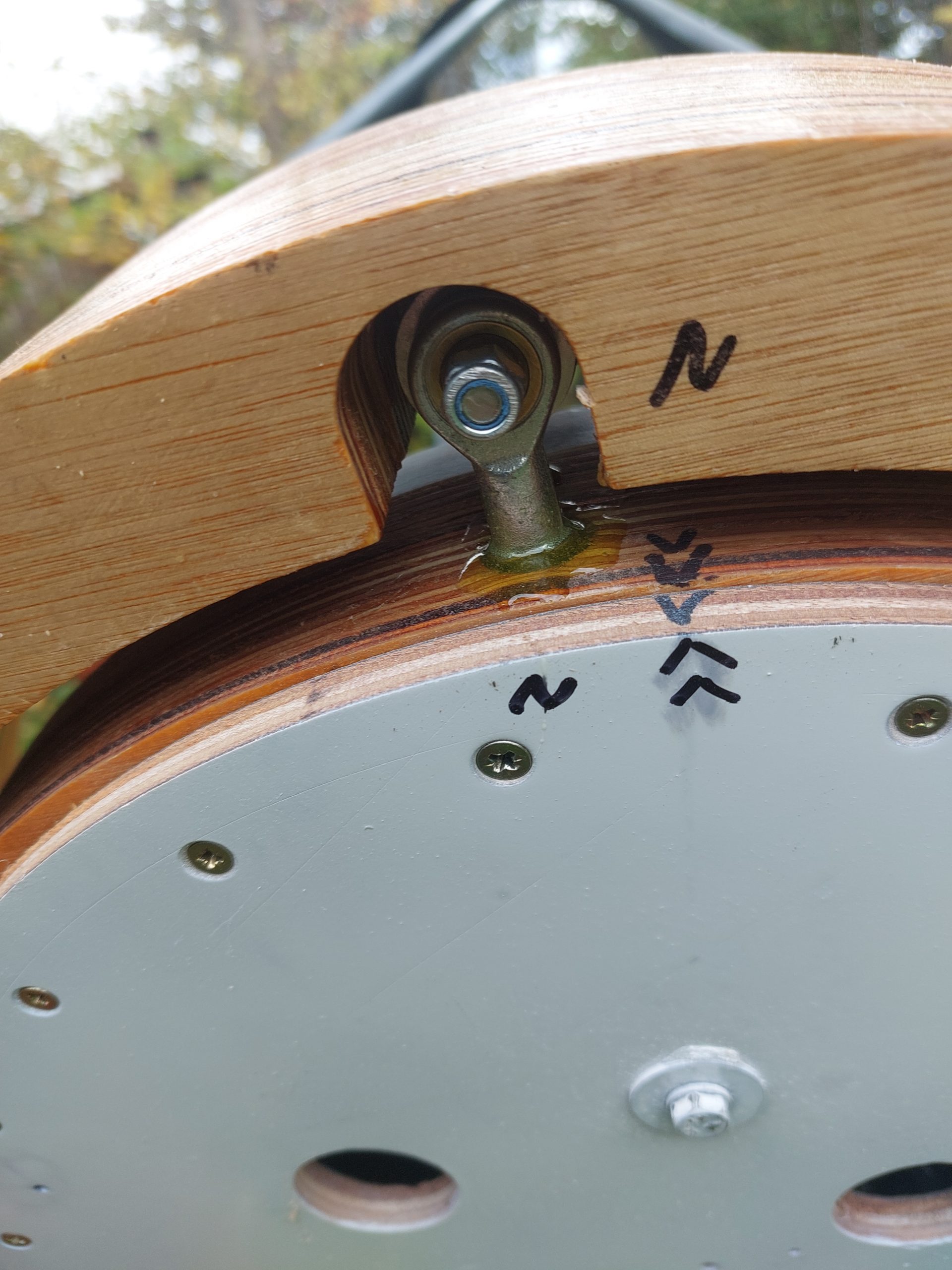
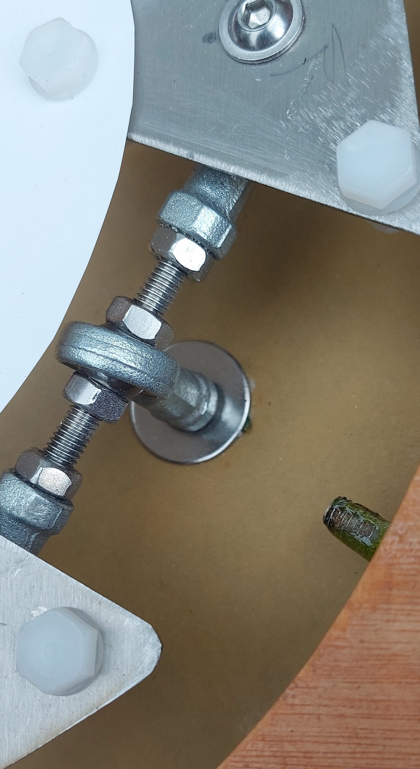
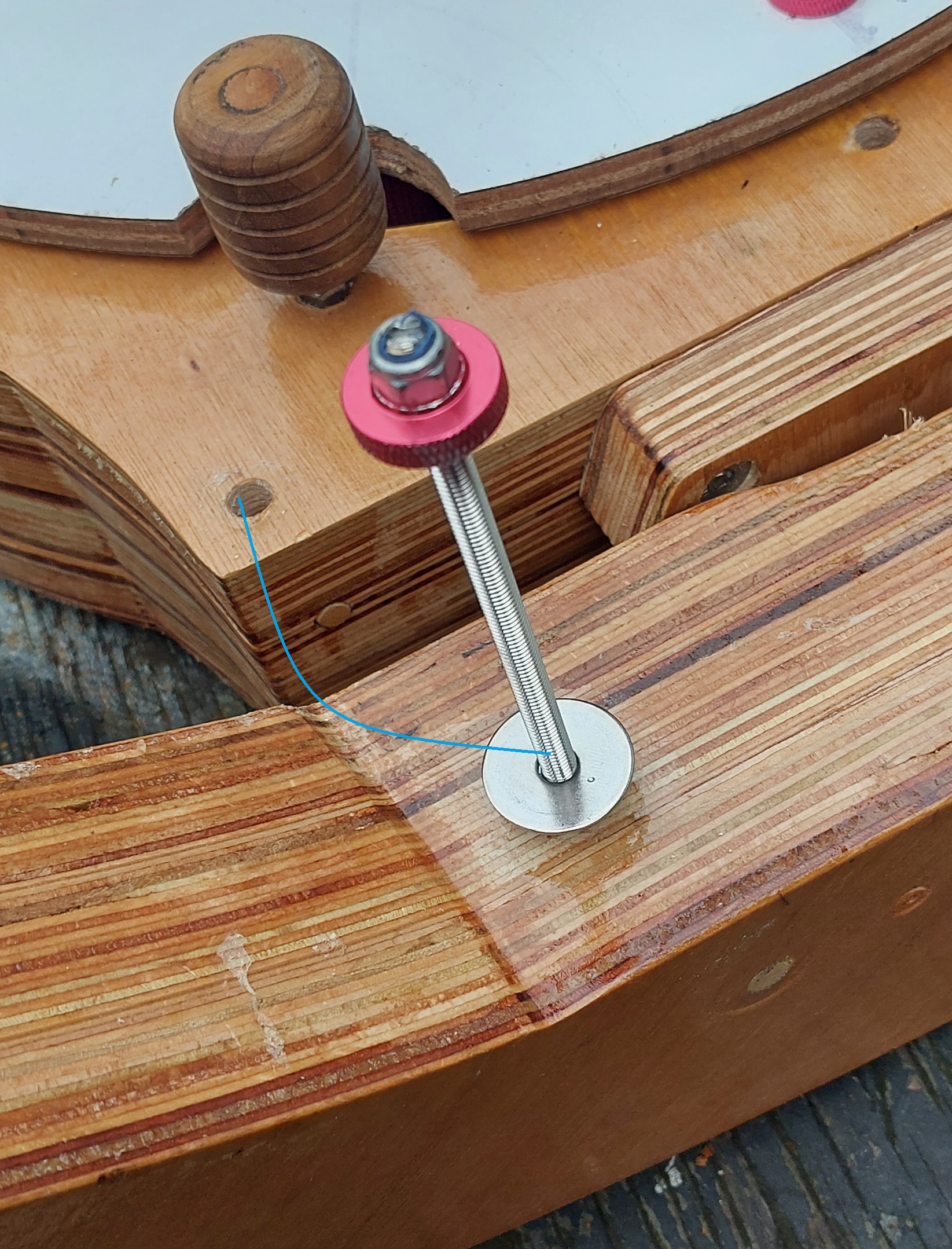
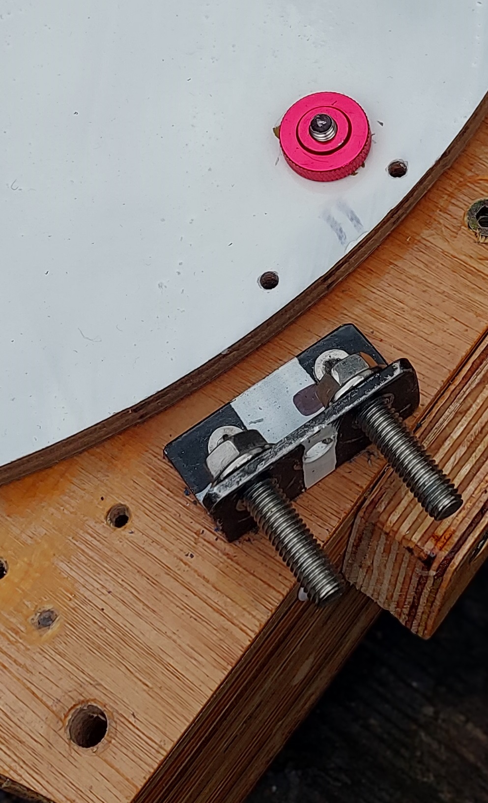
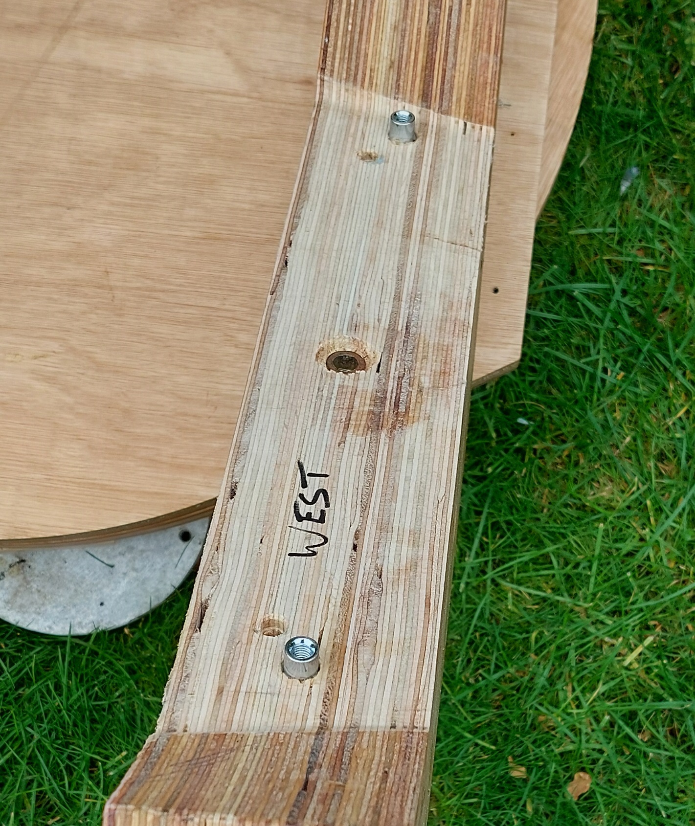
The following three images show:
The threaded bolt that fastens the primary mirror box/cell on top of the altitude bearings.
The bracket and 8mm bolts that secure the bottom end of the six struts.
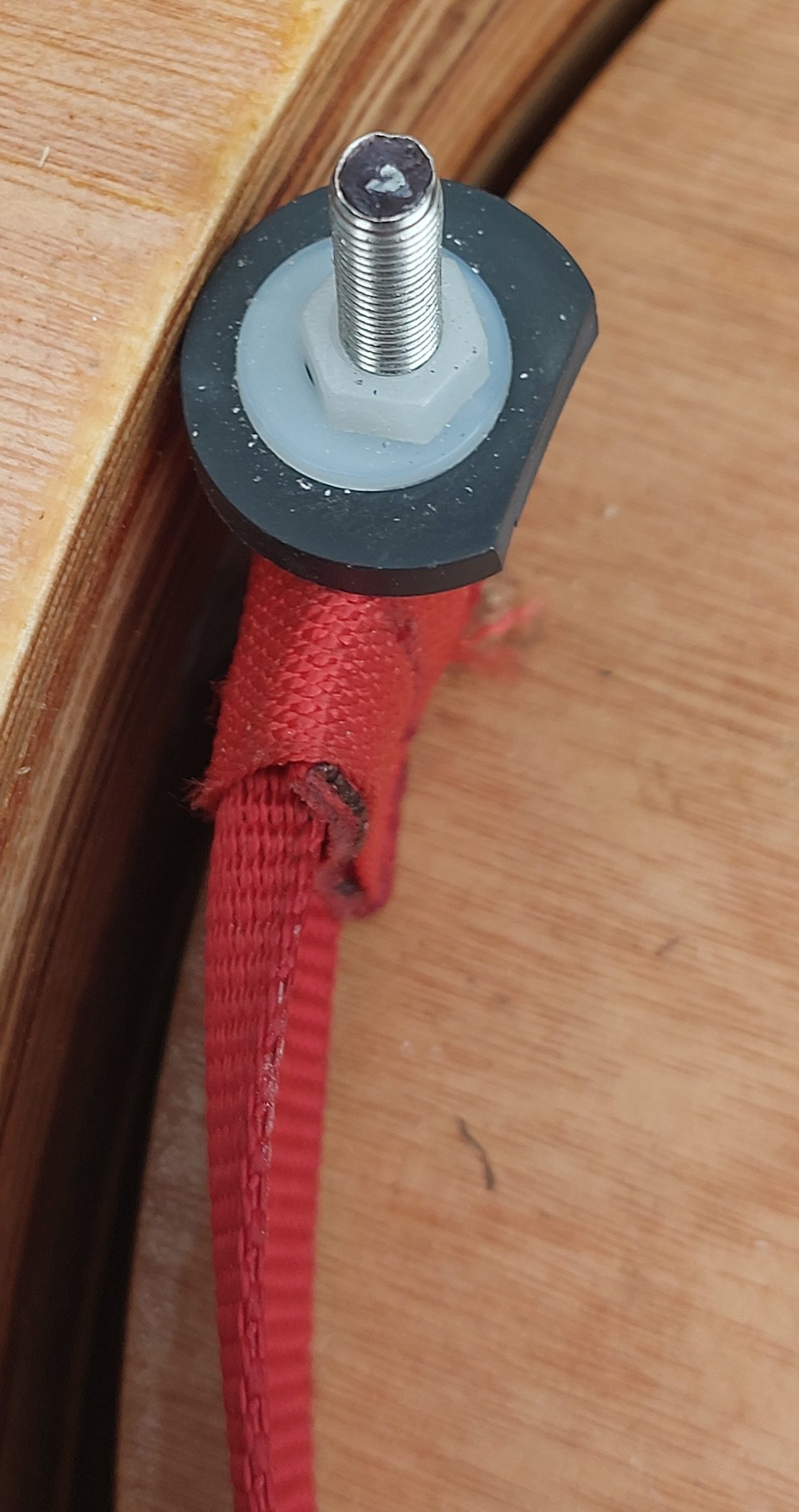
The primary mirror strap post.
^mm threaded rod glued in place.
Threaded sleeve (not visible) which the strap end loops around.rubber washer that (when turned 180 degrees) overlaps the mirror edge and stops it falling out of the box.
plastic nut.
The rod protrudes through the mirror cover and is locked in place for transport.
alt bearing bolt
Clamps for strut bottom
Mirror strap post
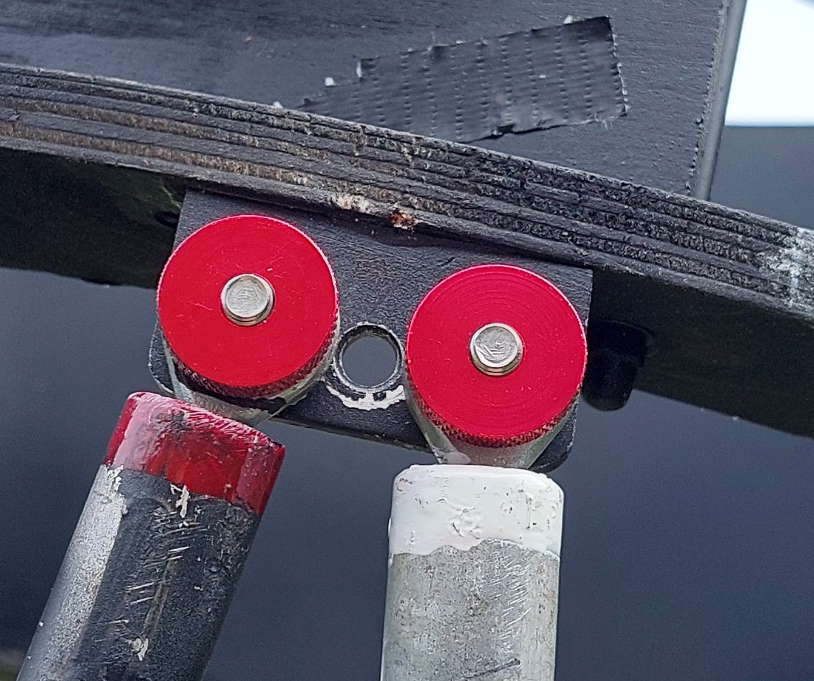
The altitude bearings rest on teflon blocks (25mm x 18mm), two per bearing.
As the groove in the bearing is 25mm, and the plywood the teflon blocks sit on is also 25mm wide it’s essential to shave off a little thickness from the runners so the bearings can freely move.
Barrel nuts are used in several places on the scope. Here I’ve left them slightly proud of the altitude bearing top. They act as a locator pin for the mirror cell assembly which is first located on top of the two bearings then securely bolted down using four 6mm bolts.
Altitude bearings on baseboard
Barrel nuts
Final "slim-line" altitude bearing base
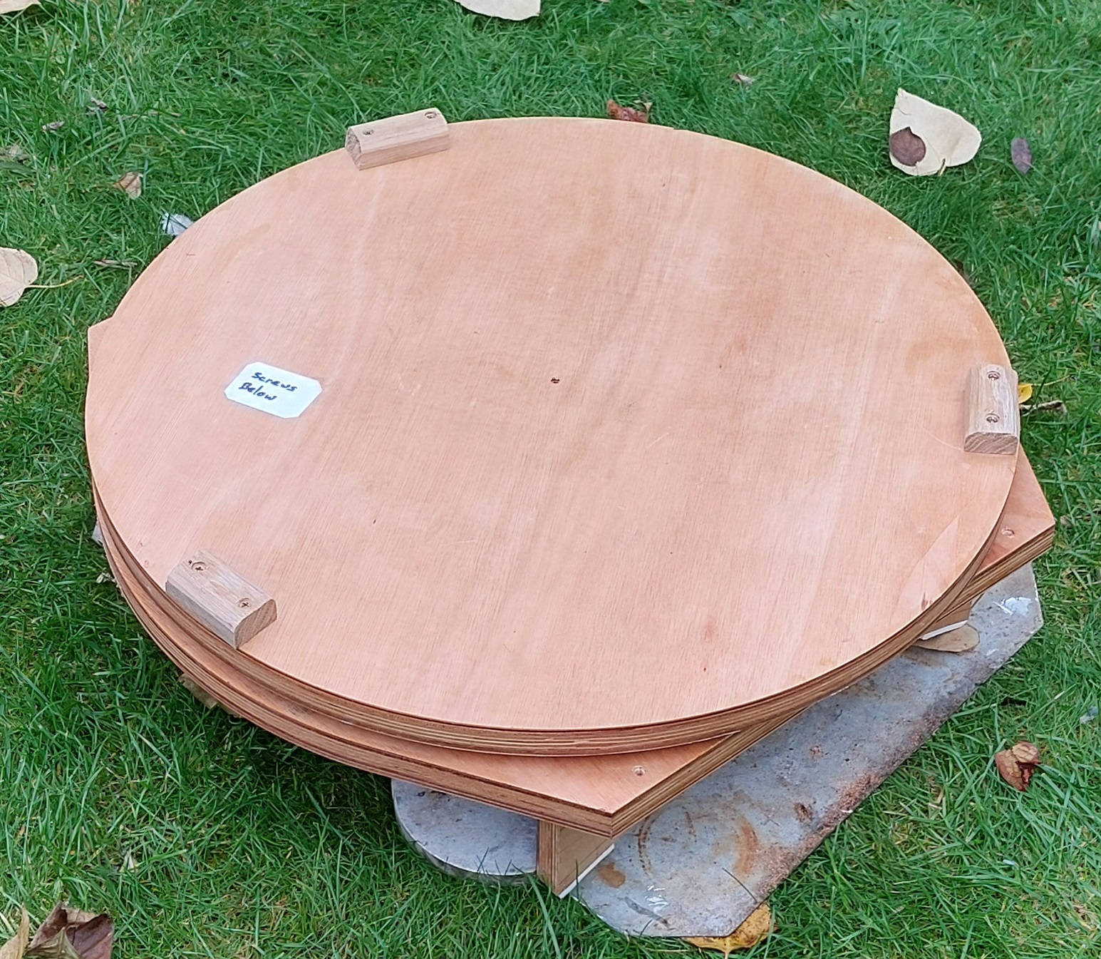
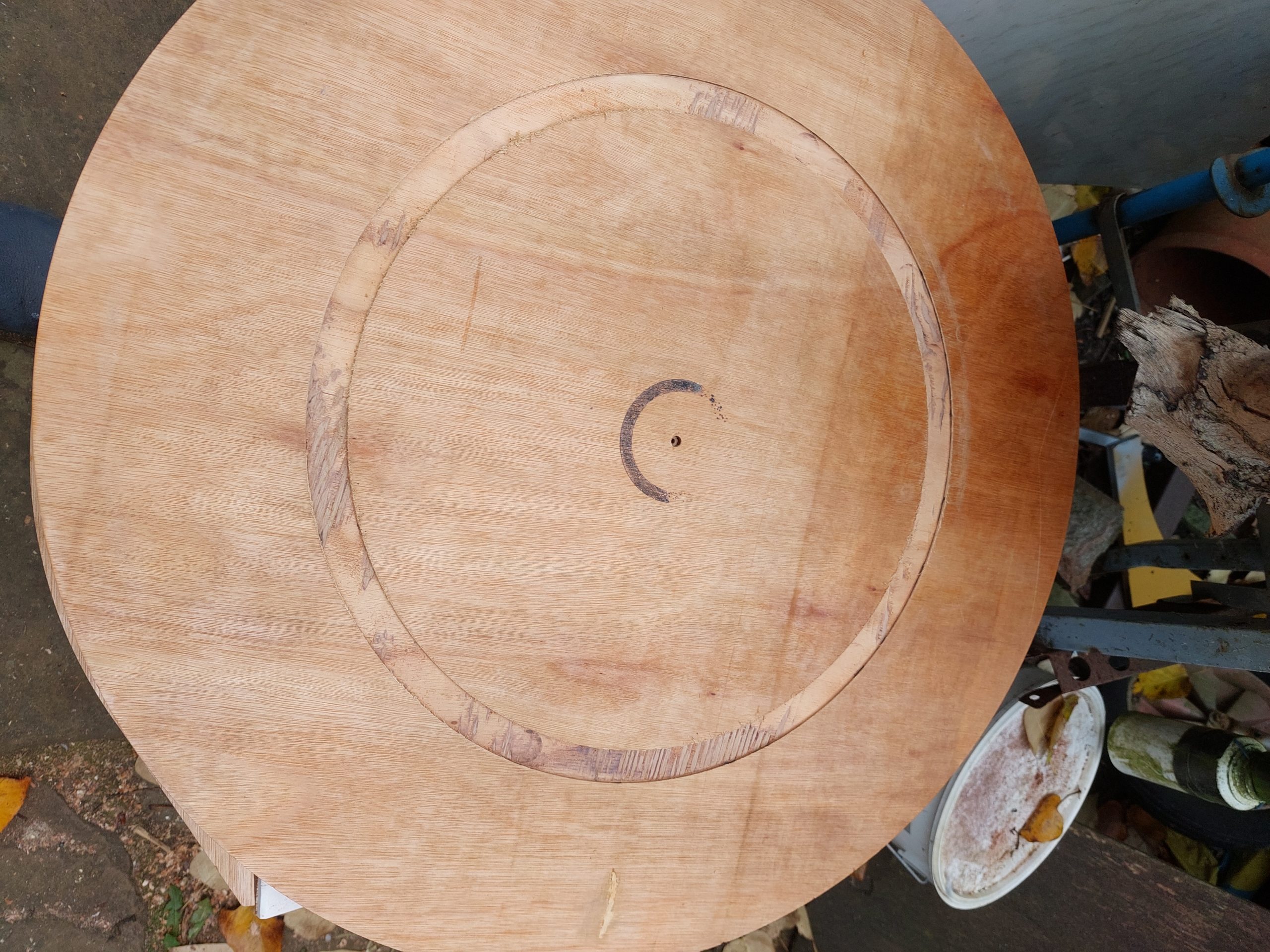
Baseboard
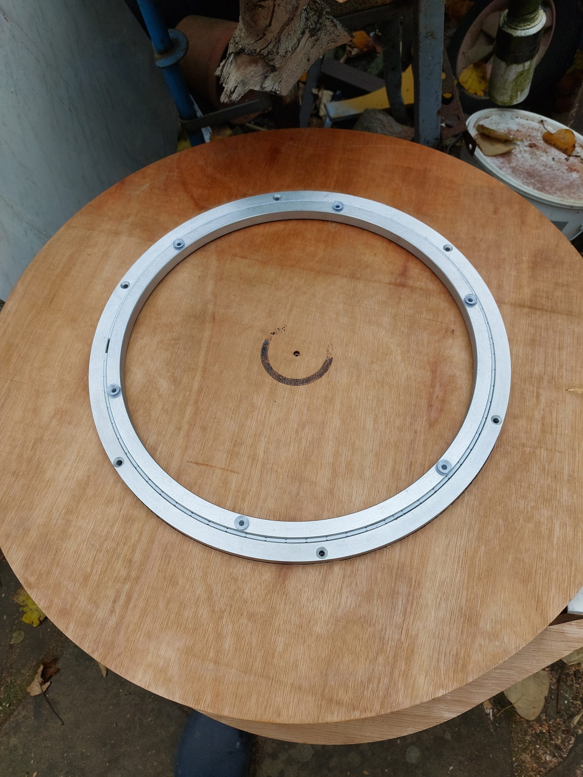
This is the simplest part of the scope. A 620mm diameter disc forms the bottom, with a similar shape for the top. The base sits on three oak blocks and the azimuth bearing is a 400mm Lazy Susan bearing from Ebay. I will be fitting setting circles sometime in the near future.
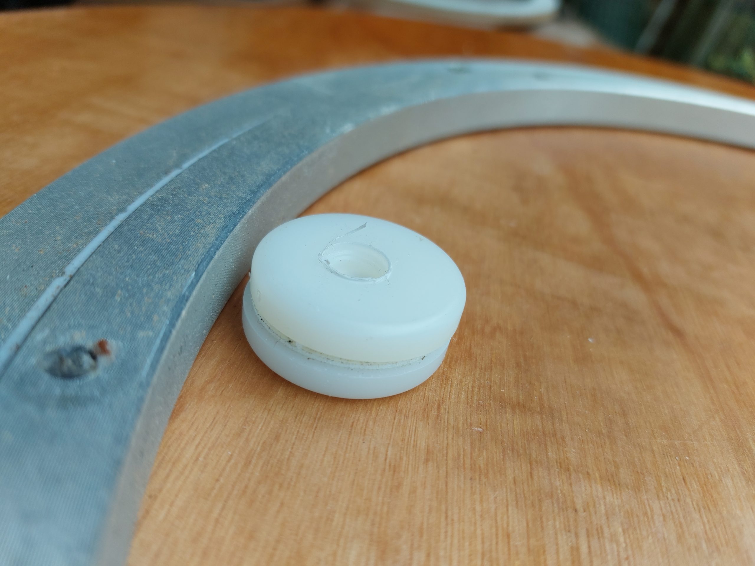
The disadvantage of the Lazy Susan bearing is that it is too good, the mount moves too freely under the slightest pressure.
I have added a brake to restrain this movement. Three pairs of plastic buttons happened to be just the right thickness give a little (but not too much) friction to the azimuth movement of the mount meaning it will stay where pointed unless I move it.
Bottom baseboard with oak feet
shallow grooves help locate the bearing
Lazy Susan is screwed into place.
1 of three double buttons
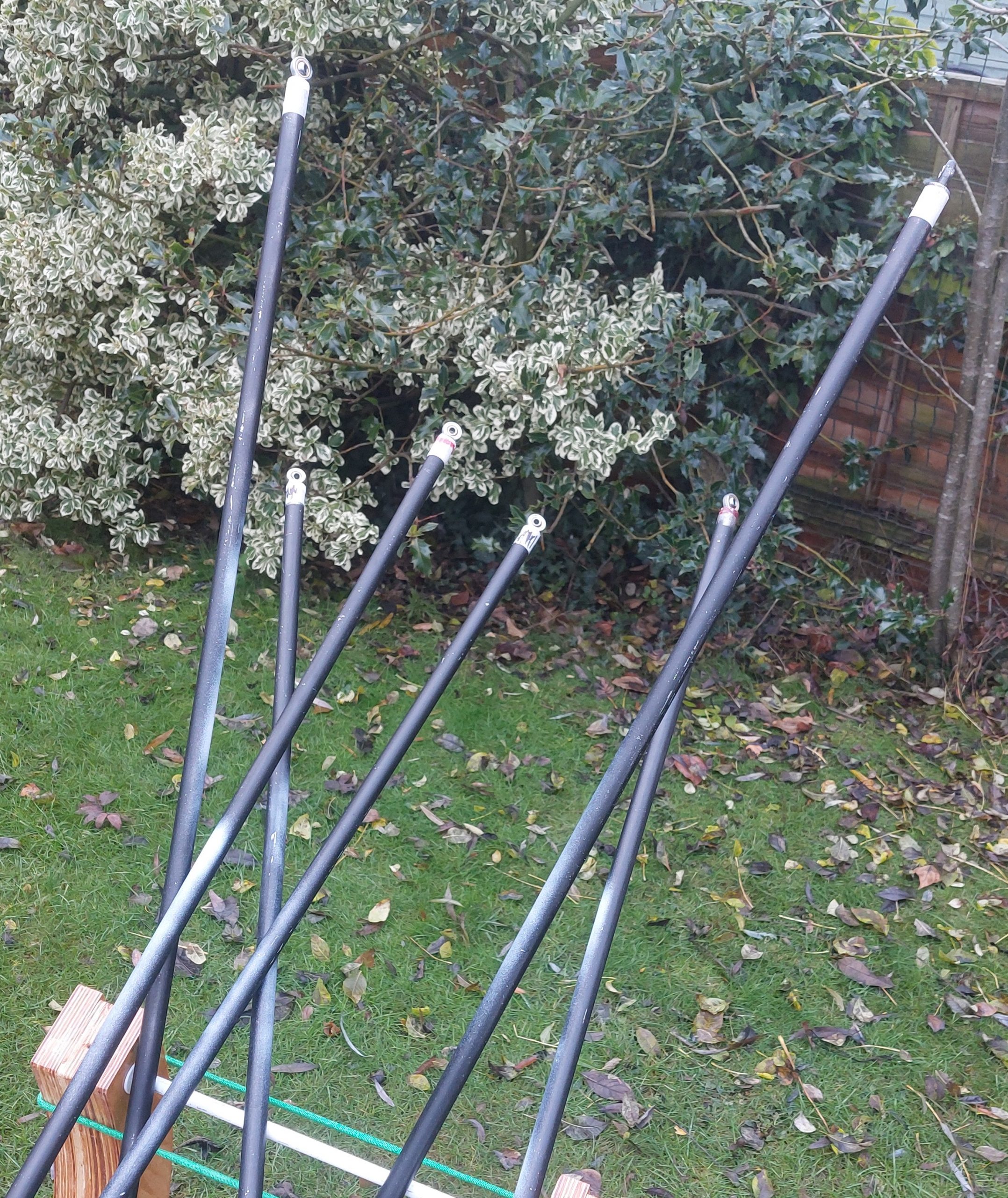
The Struts
In Kriege and Berry’s excellent book The Dobsonian Telescope, a practical manual for building large aperture telescopes there’s a section on selecting the correct diameter and gauge of pipe for the struts of a telescope.
I didn’t use this. I had 7 lengths of aluminium pipe available and they seemed to be ok. They are of a smaller diameter than the recommendation, but a thicker gauge which compensates. It is possible I will have to change the tubes, but for now they seem adequate.
I opted for a three-way strut arrangement rather than the four-way layout as the primary mirror “box” is circular rather than rectangular.
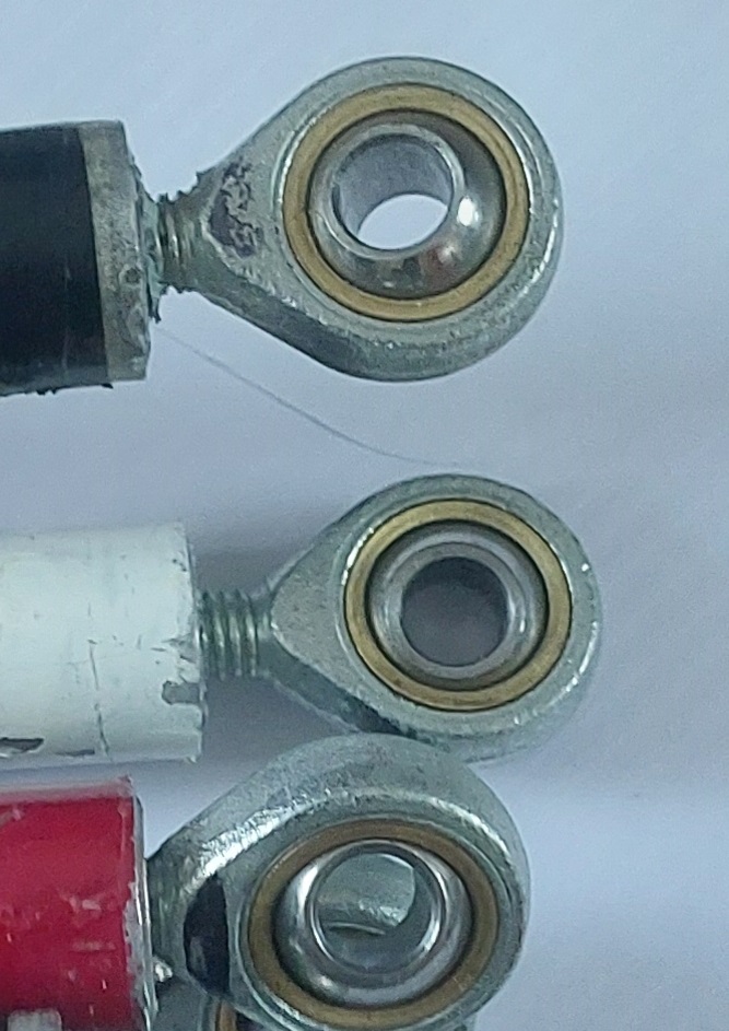
Initially the ends of the struts were fitted with balls that fitted into sockets, but I changed that to a more secure bolt and nut arrangement. The primary mirror strut ends are aluminium brackets with two 8mm stainless steel bolts (now 30mm long), while the secondary mirror is attached using 6mm bolts and nuts.
The strut ends are made up of 6mm and 8mm threaded eyes. The eyes are glued in place using high strength car body filler. A nut is embedded in the filler and the end eyes can be screwed in and out.
Clamps for strut bottom
6mm or 8mm end eyes glued into aluminum poles
Struts fixed to the primary mirror base, Awaiting the mounting ring.
mounting ring attached to struts
Focal Length determination: method by John Dobson – place mirror on the floor upright against the wall or on a stand. Then take a flashlight and a piece of cardboard and go to the estimated radius of curvature (twice the focal length). Shine the flashlight into the mirror with the cardboard right next to the bulb in the flashlight. Go forward and back (board and flashlight together) – when you see the bulb assembly in focus you are at the radius of curvature – this is TWICE the focal length of the mirror.
Setting circle for Dobsonian: I’ve fitted these to my own 8″ and current 12″ Dobs, plus 6″ and 10″ Dobs owned by my Club. The 14″ will shortly get this most essential of upgrades. More information here.
Assembly and Disassembly.
Layout all the parts on a waterproof tarpaulin to keep them dry and clean.
1. Place the baseboard on a mat.
2. Place the two altitude bearing on the bearing supports.
3. Place the primary mirror box on top of the bearings:
Locate the bolts onto the threaded sleeves and finger tighten.
Add the stretcher bar and bungee cord to the other ends of the bearings.
Ensure the box is sitting square and fully tighten bolts.
4. Fasten the struts to the base lightly using 8mm nuts.
5. Attach the mounting ring to the other end of the struts using 6mm thumbnuts.
Ensure correct orientation is achieved.
6. Attach the secondary mirror assembly to the mounting ring and tighten all three mounting nuts.
7. Tighten all nuts and thumbnuts
8. Align secondary mirror and collimate telescope with laser collimator.
Parts for CNC
The parts sent for CNC machining out of 25mm hardwood plywood are clearly shown in this CNC Parts pdf.
Hope this helps you with your project. Any questions or photos of your work – please use the Amateur Telescope Making Group on Facebook (https://www.facebook.com/groups/53726587812/)